A lot has been written about Sampling and the basics of digital audio, so I’m just going to be brief and focus on what you need to know for the rest of the blog, and also address some misconceptions
Sound, Microphones and Analog Audio
We can think of sound as waves in the air where the peaks are where the air is slightly more compressed, and the troughs are where the air is slightly less compressed. Using a microphone, it’s possible to convert these changes in air pressure into changes in electric voltage: the higher the pressure, the higher the voltage. [Note: I’m waving my arms pretty hard here. I’ve been told some microphones are sensitive to velocity, not pressure, and some produce changes in current or resistance rather than voltage, so if you want to know the gory details, please look elsewhere.] The voltage that comes out of a microphone is usually quite small, so usually you need an amplifier to bring the voltage up to a useful level. In pro audio circles this amplifier is called a “pre-amplifier” because it comes before other processing.
In an ideal microphone and amplifier, the voltage changes over time in exact proportion to the air pressure. If you graph the air pressure going into a microphone and the voltage coming out, they would have identical shapes. The voltage is analogous to the air pressure, which is where the term “analog” comes from. Analog to Digital Conversion
Analog to Digital Conversion

If we want to use audio on a computer (or iphone, or microcontroller, or whatever), we need to convert it into something computers understand: numbers (or digits, hence the term “digital”). This is exactly what an analog-to-digital converter (ADC) does. An ADC measures “samples”, the voltage at regular intervals. It turns out, if you do this fast enough, you can recover the original wave perfectly using a digital-to-analog converter (DAC). A little math tells us that we need to sample at 2 times the highest frequency in the signal to get the original, analog signal back perfectly. So, if human hearing goes up to about 20kHz, we need to sample at least 40kHz to maintain all the sounds we can hear.
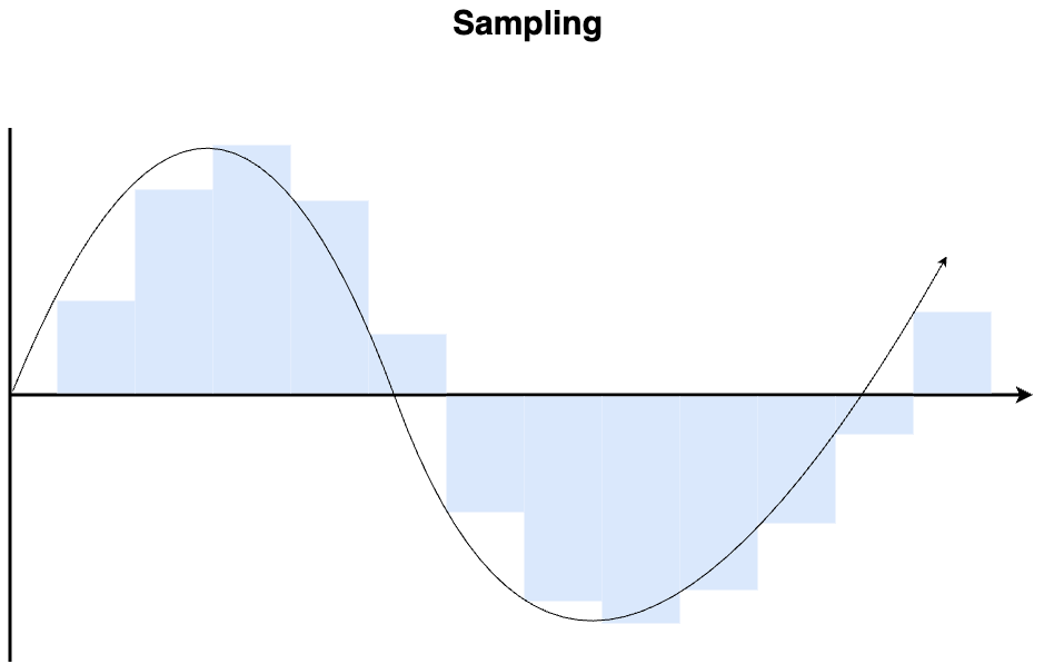
If you take the sampled version of the signal and graph it, you get something that looks a bit like a staircase, even if your original signal was smooth. This leads many people to conclude that this is a problem with digital audio or even that this is why digital audio sounds bad. Monty Montgomery does a nice job of busting this myth, so let’s take a look at some of the real issues that can crop up in ADCs.
An Example Converter
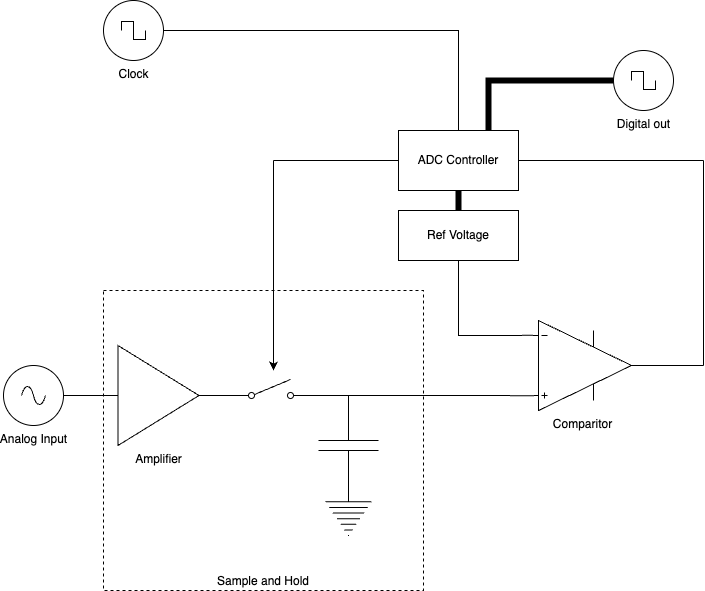
There are many ways to convert digital to analog, but we are going to take a look at one kind of converter called a successive approximation ADC. This type is not widely used for audio, but it is still illustrative of some of the issues that come up in audio. I have used this type of converter for audio when that’s what was available on my microcontroller, but fortunately it wasn’t a situation that called for high quality. Here’s how it works:
The incoming analog input goes to the “sample and hold” system, where it is amplified and the voltage is stored in a capacitor at regular intervals (the “sample rate”). In an ideal system, the capacitor voltage jumps at each interval – this is what creates the “Stair step” graph of figure 1. The capacitor is then connected to the input of a comparator, which compares the voltage to a specific reference voltage. The output of the comparator indicates if the voltage is higher or lower than the reference voltage.

Typically, the reference voltage starts at the middle of the scale. An ADC controller adjusts the reference voltage after each comparison to eventually narrow in on the correct value. After each measurement, one bit of information is added and the true value of the input is narrowed down. Multiple comparisons must be made before the next sample comes in. For this reason, the clock for the entire system needs to be running very fast: at least the sample rate times the bit depth. For CD quality audio, this would need to be 44100*16 = 705.6kHz in order for the ADC controller to choreograph the entire process.
Problems with Conversion
So, what can go wrong here? Unfortunately a great deal. First of all, recall that in order to reconstruct the signal perfectly, we said we needed to sample at twice the highest frequency in a signal. If the incoming signal contains something above that, even if the rest of the converter is perfect, a distortion called aliasing will be introduced. Because this kind of distortion is particularly unpleasant, even a small amount of signal above the threshold frequency is enough to ruin your day. Filtering out the high frequencies is virtually impossible to do without impacting some of the low frequencies, so modern ADCs solve the problem using something called “oversampling”: they sample at a much higher rate, and use digital filters to bring the effective sampling rate down. Fortunately, modern converters do an excellent job of this, so nowadays you rarely hear aliasing.
Another issue is that the reference voltages used may not be perfect. These imperfections can cause harmonic and inharmonic distortions, which are essentially impossible to resolve once the signal is converted – they will be “baked in” to the converted signal permanently. Modern converters use a variety of techniques including negative feedback and even high-frequency noise to virtually eliminate this problem.
Finally, if the clock source is not perfect, the timing of the samples will be slightly off. If it’s too fast or too slow, the recording will play back at the wrong speed, which is bad enough, but if the clock timing is sometimes to fast and sometimes too slow, the resulting “jitter” creates distortions that will also become baked in.
This is an issue that is usually minimized by having a high quality clock source close to the converter, which, ironically, is sometimes easier to do in consumer electronics than in pro audio gear. Pro recording studios often have dozens or hundreds of converters, all of which need to be tied to the same clock. This means some of the converters will be further from the clock than others, and the ones further away will experience more jitter.
While many people think the most important thing in reducing jitter is a high quality clock source, what really matters is the quality of the clock signal at the converter. The quality of the clock signal can be easily degraded by capacitances in wires so keeping the clock as close to the converter as you can is usually the best way to minimize jitter. So, while having a high quality clock is critical to modern digital recording, the solution is not a 6 thousand dollar clock that will be placed, at best, a few inches away from your ADC, because such a device is inevitably going to be placed further from the converter than the converter’s internal clock.
Of course, the reality is that the internal clock can’t always be used – you might have multiple converters that need to be synchronized to the same clock. In this case, at least one of the converts will be using an external clock. Careful processing of the clock signal is needed to keep the sample rate stable and produce a high quality clock signal for all the converters.


